DIY LED ~ easy build thread

Muddskipper35

Non-member
First this thread is what it is. Please do not complicate it. Feel free to ask questions and make suggestions and I will try my best to answer them.

Items bought.

24LED kit with 0-10v dimmable ballasts from RapidLed.com
ordered this kit with 60degree lenses. $285

2 24ft rolls of 16 gauge wire *Should have used 18 as this would have been best for this build and easier to solder. $10 -$5each

New soldering gun and tips. $10 harbour freight

ROSIN core solder 60/40 *DO NOT USE ACID CORE this will corrode and eat you electronics. $7 HD

Thermal adhesive paste~ My kit was not shipped with it so I bought mine at radio shack $3

3 potientiometers to build a controller for the dimmers on the ballasts ( not needed if using RKL-AC module or APEX) this was temp unti I work out the alc module .. $2.99 each = $9 radio shack

1"X48" square aluminium stock for heat sink. $10 HD

48 screws 4-40 .. $?? cheap HD

Liqued ele. tape $8 HD

9volt wall adapter *word of caution.. It might say 9volt output but measured will really be putting out about 12v. $Free you probably have some laying around the house. Old printer, battery charger, ect... Not needed if using an RKL_ALC or APEX

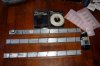
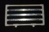
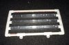
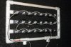
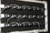
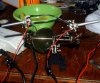
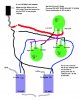
The following pics really explain everything except the pots used to test the array.

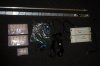
There are 3 pots used. First one is to set the voltage at 9.9volts. DO NOT READJUST THIS POT . From this pot the output goes to the other 2 pots which are then wired to the ballasts to control the dimmable ballasts.
If you need me to post a diagram of this let me know.

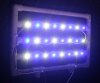
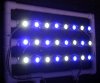
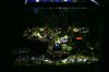
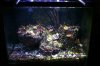
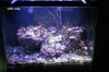
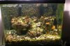
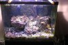
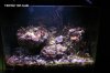
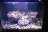
The 2 pics of the tanks-
1rst is set at 1volt on the dimmer. Lowest setting.
2nd is set at 9.8 volts on the dimmer. Highest setting.
 

Attachments

  • 1.1.jpg
    1.1.jpg
    39.1 KB · Views: 557
  • 2.1.jpg
    2.1.jpg
    47.7 KB · Views: 560
  • 3.jpg
    3.jpg
    36.7 KB · Views: 564
PAR AND TEMPS

Measurements taken 10" an 13" of depth Fixtture is 3" above the waterline.
Voltage given for each measurement of input into the ballasts.

Voltage 13" ~ 10" temp on heatsink
9.9 120 ~ 181 159degrees
8.0 106 ~ 157
7.0 99 ~ 148 139degrees
6.0 86 ~ 132
5.0 74 ~ 113 121degrees
4.0 61 ~ 100
3.0 47 ~ 80
2.0 34 ~ 48
1.0 15 ~ 22

And the results of each individual color at the same settings and depth.
RB= royal blue and CW= Cool Whites measured at only 13" depth

Voltage 13" RB ~ CW
9.9 64 ~ 57
8.0 56 ~ 52
7.0 50 ~ 49
6.0 45 ~ 44
5.0 39 ~ 39
4.0 32 ~ 32
3.0 24 ~ 26
2.0 14 ~ 17
1.0 6 ~ 8

Interesting results.
 
The above results were taken WITHOUT LENSES. as I have a better spread of light and asthetics I will NOT be using lenses on the LEDS.
The PVC on the fixture was used only to test the array and will be removed after I retro the 400mh canopy.
 
Nice build! Do you have any more pics of the circuit you used to control the input voltage to the meanwells to make sure you don't go over 10 volts. It doesn't look like you used a lm317 attached to those pots. Just curious on what you used!
 
nice build, i like the thinking outside the box for heatsinking ideas, how did that work out for you? any temp reading?

im interested in the dimming circut as well
 
Doc- The temps were posted in with the par readings. I didn't take lower numbers under 120 degrees at 5volts input as below that I really wasn't concerned. I was concerned about the higher numbers so as not to melt the PVC .. 160 degrees was the hottest I measured on the heatsink and this was sabilized for 1 hour between readings. There was no fan or air movement across the heat sink durinng the time the readings took place. I may keep the pvc after I hook a fan up to blow air through the pvc and heatsinks and take temp readings. Have to see what the readings look like.

As far as the controller~ I'll have to draw it up and post it. It's really pretty easy (although it had been so log using pot's I had to look them up to remember how to wire them) Once ya see the pic you'll laugh..
 
the place to take temps on leds is actually on a solder pad i beleive, then there is also some kind of calculation involved, but 160 on a heatsink with no fans sounds pretty good i think, im going to look it up now actually since i have an IR thermometer on the way

the datasheet says 90c=194f for the 70% maintinence to 50k hours, sounds like you might be on to something, assuming that your leds are well attached, which i bet they are since you tapped and screwed.
 
Last edited:
The LEDS are tapped and screwed and have a therma paste underneath each pad to help conduct the heat away. I dont have any means to test at the pads right now. I ran the setup at 7 volts input as I will for about a week to match the par output of previous light, then I will slowly increase the output of the LEDs each week until I can max them out at full output.

AND NOW...

The wiring diagram for the pot controller for the meanwell dimmers.!
 

Attachments

  • Untitled-1 copy.jpg
    Untitled-1 copy.jpg
    70.6 KB · Views: 530
Questions?

Pot 1 can be secured using liqued ele tape to help insure it doesnt move.
The 2 squares on the bottom are the meanwels.
There are no resistors or missing pieces.
I would not use a wall adapter with high amps. If I remember right they can handle 1.5 amps ( dont quote me) but its only looking for a signal so stay on the low side.
Yes all grounds run to the wal adapter- each pot and the dim - on the meanwels.

I set the POT1 at 9.9v and after I hooked up the meanwels and adjusted pots 2 and 3 I checked the voltage at each and adjusted pot1 again to to 9.9 volts. I would recommend double and triple checking this ..
 
Last edited:
Nice build.... I'll be paying attention as I plan on doing an LED retro in 3-6 months on my tank...
 
Different results and mixed results .. Pics below..
I might start leaning towards a hybrid......... hmmmmmm.....
 

Attachments

  • A copy.jpg
    A copy.jpg
    38.3 KB · Views: 491
  • B.jpg
    B.jpg
    45.3 KB · Views: 514
  • C.jpg
    C.jpg
    41.1 KB · Views: 492
  • D.jpg
    D.jpg
    32.3 KB · Views: 506
  • E.jpg
    E.jpg
    43.2 KB · Views: 513
Can't remember if you've said this or it's been brought up but have you dimmed the LED's to get a different look? I know people have dimmed down the blues to adjust the coloring to their liking...
 
Yes but for the pics and results posted I wanted the max out of the leds for most par and the 14k look to give comparisons. Yes this can be dimmed for a 10k to 25k look and with just the cool whites and no blue it looks like ( to me) about a 7500k rating .. gonna have to look up the specs again on the leds for color ratings.
 
Back
Top