Arduino Reef Controller Build

Frag Freaks

Well-Known Member
BRS Sponsor
BRS Member
Well here we go. As I mentioned in my 120g Mixed Reef build thread, I am going to attempt to build my own controller.

Project Overview

- Temp Monitoring
Sump, Canopy
The heaters will be controlled by the DT temp, the sump will just be an extra monitor to distinguish the difference (If any) between the two. The Canopy temp sensor will control the on and off of the fans that will be located in the canopy. I will also have the lighting linked to the DT sensor to turn off if the tank temp becomes to high.

- Lighting Control
Simple on/off control feature. One to control the main lighting system, Second for the Refugium Lighting, and Third for the moonlights.

- Wave-maker
Simply On/Off oscillations between the associated pumps in the main tank.

- Feed Mode
Will turn off the circulation pumps in the DT for a certain period of time.

-Auto Top-Off
Based on a liquid level sensor in the sump, this will trigger the top off pump.

pH Monitoring
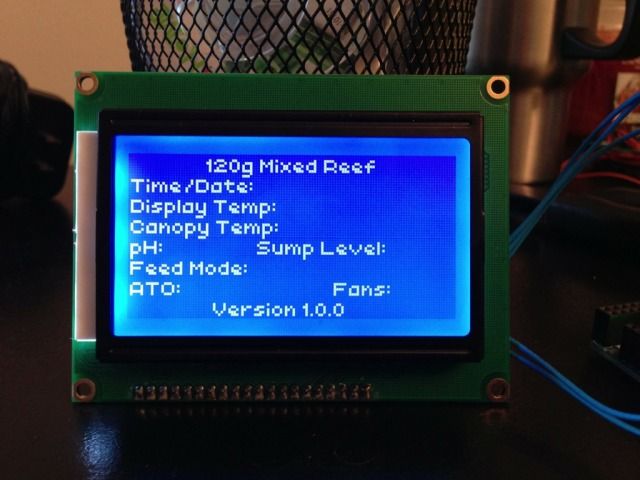
Display the pH of the tank on the main screen of the controller.

Here is a list of what I have coming (so far):
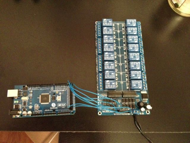
- SainSmart Mega2560
- SainSmart Prototype Board
- Mini Breadboard
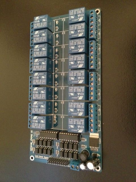
- SainSmart 16 channel relay module
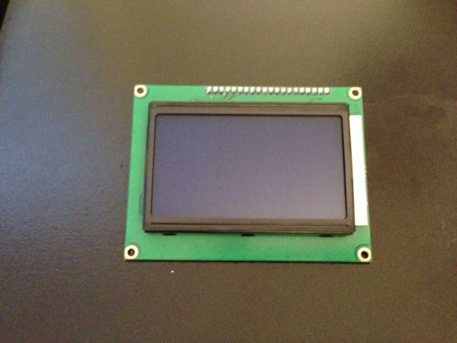
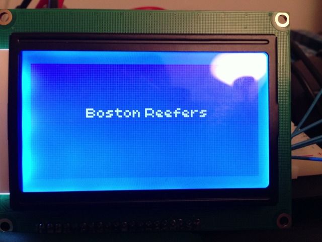
- 128x64 Blue backlight LCD
- Power Supply

Sensor List:

- Waterproof Temp Sensors (QTY: 2)
- Real Time Clock Module
- Liquid Level Sensor
- pH Probe Kit

Future Possible Options:

- Constant Salinity Monitor
- Audible Alarm for when the Levels in the tank are off (Temp, pH, Salinity)
- RO Chamber water level indicator - To let me know from outside the tank that I need to refill my RO water
- Ethernet Shield to display all tank levels via a website for out of home monitoring
- Camera to be able to view tank action
- Led Panel to indicate which relays are on.

Once I get everything up and running I will mount it all up in some nice enclosures to give it a cleaner look. I don't know how long this will take me but be patient with the updates. Some of my ideas my change as I get going.
 
A few things came in the mail today:

The LCD:
6A1A3931-49C2-4B44-85CC-FCB758659347-6032-00000241A0DD0B38.jpg


Sainsmart 12V 16 Channel Relay Board - I decided to go with the 16 channel over the 8 channel so that I would have some flexibility with some extra add-ins down the road.
E6704CA7-05BA-431E-9F6D-CC43F2A36C80-6032-00000241AAE4948E.jpg


External power supply for the Mega2560. This will be used just for some small scale tests (playing around with the LCD, sensors etc). I will end up running a 12v adapter that the relay board needs which in turn will also feed the controller itself (or so thats what I assume after some research).
33EC4AA3-61A3-4283-A547-B55A457DB89B-6032-00000242727212AB.jpg


I am still waiting on the micro controller itself before I can really start playing around with this. Hopefully it comes soon. Should be due in any day now but with the holidays it could be delayed.
 
Have you figured out what the savings will be by it being DIY? If it is cheap enough I would like to try it also
 
Have you figured out what the savings will be by it being DIY? If it is cheap enough I would like to try it also

I looked into this before I bought my controller; actually have an Arduino board and some temp probes I got online for free on my shelf. Unless you like DIY and have the soldering skills/etc., you're better off just buying an Apex Jr or ReefKeeper Lite. By the time you get all the components it'll cost you more. Never mind the time you need to put into building it, coding it, etc.
 
I looked into this before I bought my controller; actually have an Arduino board and some temp probes I got online for free on my shelf. Unless you like DIY and have the soldering skills/etc., you're better off just buying an Apex Jr or ReefKeeper Lite. By the time you get all the components it'll cost you more. Never mind the time you need to put into building it, coding it, etc.

Thats what I noticed with DIY led builds. But then again you cant put a price on experience and sense of accomplishment.

By no means am I diminishing what you are doing I thinks its great and will be following along like its Jersey shore
 
By no means am I diminishing what you are doing I thinks its great and will be following along like its Jersey shore

Neither am I. I want to do something with my board, I just haven't found the time to do it. At a minimum I'd like to get an LCD and a relay board. Maybe set up another temp probe and some additional outlets.

I'll be tagging along to see the OPs progress.
 
I agree and disagree at the same time.

I agree with the fact that if you are not into DIY and only looking to control heaters, lights etc then the Apex Jr and the Reefkeeper Lite is the way to go. I think those units cost roughly in the $200 to $250 range brand new. I have noticed that both of these units only limit you to 4 controlled outlets. If you want to get to the higher models I see them going for up towards the $400-$500 dollar range.

I have had a ReefKeeper II before and would it do pretty much everything I would, yes it would but to me its more fun in making my own. I think the build portion is really got me interested. Anyone can buy one off the shelf, but the satisfaction of making my own is what really made my decision.

With the right shopping around and research you can create a controller that will do everything and more the higher end controllers can do but at a fraction of the price.

Indeed it is not for everyone because it does take time and patience. A lot of the coding for these things have already been done and are available for people to use and modify to suit there needs so that does save some time.

I have not paid full price for any of my components this far. I had some points I could use on amazon along with a gift card. With the micro controller, pro to shield, relay board, and LCD I have only spent about $50 bucks.

Now of course that will not happen for everyone. I will document the actual sticker prices and total cost if you did not have the discounts like I have used. If you have some circuit know how you can also create your sensors for very cheap. If you buy some of the pre made sensors then the price can elevate very quickly (for example a pH prob pre made circuit can run up to almost $100)

The thing I really like about the DIY aspect is I can make this controller do whatever I need it to do and customize it to suit my tank. And If later on I want it to do something else or add something I can.
 
Following this one as well. Not really reef tank related (well it could be for acrylic projects) but I have been looking into arduino for controlling a DIY desktop 3 axis cnc router table. Also currently playing with some two channel relay boards for an auto-water change build and ATO system.
 
I will be watching this as well. I showed this thread to my son tonight. He is like... Yeah, just do this, this and this and about half a day of coding.
I sometimes question if he has my genes.

He like whipped it out on the white marker board in the den in like three minutes.

Like you said. Cost+time+parts and satisfaction of knowing you built it. Compared to just buying it off the shelf.

If course being able to code..."priceless"

I have some mild c++ programming skills that should help me with the coding. I will definitely need to freshen up a little. My plan for version 1.0 is to simply take existing code to get the controller up and running. The later versions will include some more specific coding to suit my needs better.
 
Parts List Totals

Ok, so here is a list of parts I have ordered so far and their corresponding actual prices.

Remember I did not pay full price for these parts since I had some points hanging around along with a couple small gift cards. I will include the actual prices I have paid so far as well.

- Sainsmart 16 Channel Relay $23.69 (My price - Free)
- Wall Adapter 9V 650mA $6.64 (My Price - Free)
- Sainsmart 12864 128x64 LCD $18.95 (My price - $9.33)
- Sainsmart Mega2560 with proto-shield and jumper combo $39.99 (My Price - $39.99)

Total Full Price so far: $89.27
My Total: $49.32
 
Well the heart of the controller came today. Just in time to so some playing around on the long holiday break. The proto shield also came in as well.

ImageUploadedByTapatalk1356225346.009187.jpg
ImageUploadedByTapatalk1356225418.469869.jpg
 
I did some quick playing around.

Downloaded the appropriate libraries for the LCD and got them talking to each other. Figures i bought the LCD that has the least amount of information and examples on the web. After I configured a few pins i wS able to get it working.

ImageUploadedByTapatalk1356225575.120113.jpg

Next step will be to play around with fonts and get the layout I want for the screen. Once that is done I will get to work on ordering some sensors and get the relay board going as well.
 
After playing around with some contrast and brightness, I was able to get a better output on the LCD.

9B3075C0-34D0-469B-B761-9581F7081468-3477-00000121B76D4241.jpg
 
For anyone who is interested in following this DIY and want to try it yourselves and buy the same LCD that I did, here are few tips to get your micro-controller talking to your screen.

First you need to download the proper libraries for the LCD to work. Some LCDs you might buy already have libraries that are associated in the Arduino library lists.

For this LCD, I needed to go and download and extract the files into the library folders of the Arduino software. For this screen I needed the libraries for universal graphics library for 8 bit embedded systems (u8glib).

Anything you need to know about these systems, along with the library files can be found here:
http://code.google.com/p/u8glib/

Second, once the libraries are downloaded you can go ahead and extract those files into the library folder of your Arduino software. This will now allow you to import this library into your sketches.

The line of code to do so which you would have at the begininng of your sketch is as follows:

Code:
#include <U8glib.h>

This now will import the library to recognize your screen.

The next step is to establish and indicate the pins you will be using for your monitor. It doesn't matter what pins you use as long as you tell the Arduino what they are. Each screen may use a different display controller. The controller that is being used in your screen will be in the spec sheet. Locate that controller and you match it up with the C++ Construction found here:
http://code.google.com/p/u8glib/wiki/device

In my case I am using ST7920 controller and my u8glib constructor looked like this:

Code:
U8GLIB_ST7920_128X64 u8g(13, 11, 12, U8G_PIN_NONE);       //(13 = SCK, 12 = CS, 11 = SID)

This is indicating which pins are associated with the SPI connector of my screen.

I am doing a very simple screen to start, you can get into interactive menus and such to and make it more complex. I plan to fool around with something like that down the road.

So the next part is you need to dictate what you want you screen to say and where you want to say it. The following will show a simple code to display "Boston Reefers" on the screen. This is where you would also set your font.

Code:
void draw(void) 
{
  u8g.setFont(u8g_font_chikita); //font style
  u8g.drawStr( 30, 30, "Boston Reefers");
}

The last step would be to create your picture loop so that the picture can be displayed and refreshed:

Code:
void setup(void) {}
void loop(void) {
  //picture loop
  u8g.firstPage();  
  do {
    draw();
  } while( u8g.nextPage() );
  delay(500); //rebuilds the picture after some delay
}

Now put the sketch all together and upload it into your arduino to get a full sketch as seen below:

Code:
#include <U8glib.h> //u8glib for screen recognition

U8GLIB_ST7920_128X64 u8g(13, 11, 12, U8G_PIN_NONE);       //(13 = SCK, 12 = CS, 11 = SID) 

void draw(void) 
{
  u8g.setFont(u8g_font_chikita); //font style
  u8g.drawStr( 30, 30, "Boston Reefers");
}

void setup(void) {}

void loop(void) {
  //picture loop
  u8g.firstPage();  
  do {
    draw();
  } while( u8g.nextPage() );
  delay(500); //rebuilds the picture after some delay
}

If everything is hooked up correctly you should see this:
9F42D69F-68B0-428F-B40B-7FEEE52AEF80-3477-0000012446A9F287.jpg
 
Testing Relay

So I wanted to test out my relay board to see if I can get them talking to each other.

For this particular relay which is the Sainsmart 16 channel relay, it needs a 12vdc source in order to trigger the relays. I had an old router adapter laying around which was 12v, so I decided to use that.

Here is a picture with the controller connected to the relay board:
70532C01-5666-4AD1-A62E-78C8961FD570-3591-0000012A01CB2B86.jpg


I only have 4 relays hooked up in this picture.

The coding here is very simple. All I did was take the simple blink led code example and added a few extra steps.

So the first thing to do is to define what relays are connected to which pins. In the example i am using the digital pins of the Sainsmart 2560

Code:
int relay1 = 22;              // relay connected to digital pin 22
int relay2 = 23;              // relay connected to digital pin 23
int relay3 = 24;              // relay connected to digital pin 24
int relay4 = 25;              // relay connected to digital pin 25

Once you have the relays defined, you need to specify whether this pins are inputs or outputs using the code below.

Code:
void setup()
{
  pinMode(relay1, OUTPUT);      // sets the digital pin as output
  pinMode(relay2, OUTPUT);      // sets the digital pin as output
  pinMode(relay3, OUTPUT);      // sets the digital pin as output
  pinMode(relay4, OUTPUT);      // sets the digital pin as output
}

One the controller knows which pins are connected to relays and if they are input or outputs, you need to write your code to tell them what to do. As seen in the example of the screen above I am using a loop code which will keep running the program.

In the Arduino world High = On and Low = Off. To set these relays off and on you use the digitalWrite(); function.
If you want them to be on for a certain amount of time you need to use the delay(); function. Arduino operates in milliseconds therefore 1000 milliseconds would equal 1 second.

Below is my code to show you how to turn 4 relays on and off in succession and then repeat.

Code:
void loop(){
  
  digitalWrite(relay1, HIGH); //turns on relay
  delay(1000); //runs for 1 second
  digitalWrite(relay1, LOW); //turns off relay
  delay(1000);  //off for 1 second
  digitalWrite(relay2, HIGH); //turns on next relay
  delay(1000); //runs for 1 second
  digitalWrite(relay2, LOW); //turns off relay
  delay(1000); //off for 1 second
  digitalWrite(relay3, HIGH);  //turns on next relay 
  delay(1000); //runs for 1 second 
  digitalWrite(relay3, LOW); //turns off relay
  delay(1000); //off for 1 second
  digitalWrite(relay4, HIGH);  //turns on next relay 
  delay(1000); //runs for 1 second 
  digitalWrite(relay4, LOW); //turns off relay
  delay(1000); //off for 1 second
  //repeats at beginning
}

The complete code to get your relays tested would be the following:

Code:
int relay1 = 22;              // relay connected to digital pin 22
int relay2 = 23;              // relay connected to digital pin 23
int relay3 = 24;              // relay connected to digital pin 24
int relay4 = 25;              // relay connected to digital pin 25

void setup()
{
  pinMode(relay1, OUTPUT);      // sets the digital pin as output
  pinMode(relay2, OUTPUT);      // sets the digital pin as output
  pinMode(relay3, OUTPUT);      // sets the digital pin as output
  pinMode(relay4, OUTPUT);      // sets the digital pin as output
}

void loop(){
  
  digitalWrite(relay1, HIGH); //turns on relay
  delay(1000); //runs for 1 second
  digitalWrite(relay1, LOW); //turns off relay
  delay(1000);  //off for 1 second
  digitalWrite(relay2, HIGH); //turns on next relay
  delay(1000); //runs for 1 second
  digitalWrite(relay2, LOW); //turns off relay
  delay(1000); //off for 1 second
  digitalWrite(relay3, HIGH);  //turns on next relay 
  delay(1000); //runs for 1 second 
  digitalWrite(relay3, LOW); //turns off relay
  delay(1000); //off for 1 second
  digitalWrite(relay4, HIGH);  //turns on next relay 
  delay(1000); //runs for 1 second 
  digitalWrite(relay4, LOW); //turns off relay
  delay(1000); //off for 1 second
  //repeats at beginning
}

If the code is correct you should see the following. The relays are a little loud, but once put in an enclosure it should quiet them up a bit.

[video=youtube;RJG2JTIX0Vw]http://www.youtube.com/watch?v=RJG2JTIX0Vw&feature=youtu.be[/video]
 
Back
Top