Arduino Reef Controller Build

I would also like to add that once you have the 12v feeding your relay board, that voltage supply will also run your board as well. This allows you to still only use one power adapter for the reef controller.
 
Cost Upate

So like I mentioned before I will be tracking cost of this project. I have the real sticker cost and the cost that I have spend with discounts, points, gift cards etc. Also I am not including any shipping if there was any, Since that really does not account for the actual price of parts for the controller.

So up to this point I had:

Total Full Price: $89.27
My Cost: $49.32

I ordered some more parts:

(2) DS18B20 Temp Sensort - Waterproof - $9.95 ea (I paid $9.95 ea)
Real Time Clock Module - $14.95 (I paid $14.95)
Float Switch - $4.76 (I paid FREE)
Button For Feed Mode - $1.95 (I paid $1.95)

Total Full Price: $130.83
My Cost: $86.12

I have already received the temp sensors and the real time clock and have them all set up and running. I will be updating soon with some pictures along with some coding to help anyone else who will be interested in doing the same.
 
My arduino setup has been running strong for a year and a half now. Runs my leds, heat, ato, I paired those mechanical relays with a 4 gang electrical box. I also did a separate wavemaker circuit that uses a solid state relay and has been running for ~8mos strong if you're interested. Completely worth while project, much cheaper than a retail controller.

http://www.bostonreefers.org/forums/showthread.php?111982-DIY-Arduino-Controller

Happy to see someone else has tried this as well. I will have to go through your thread and see how yours came out.
 
So, I haven't done much coding as of late. I do have my clock up and running along with the temp sensors running. I will update with some coding of those steps soon.

Before I go into phases of compiling code to actually turn relays on and off with temp and so on I wanted to get everything mounted in my project boxes so I can have all the wires tucked away nicely and just focus on finishing my program.

Here are some pictures of my progress so far.

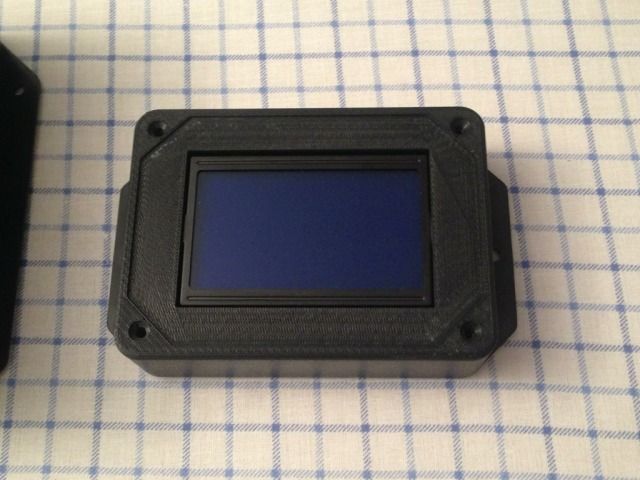
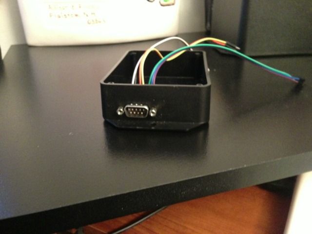
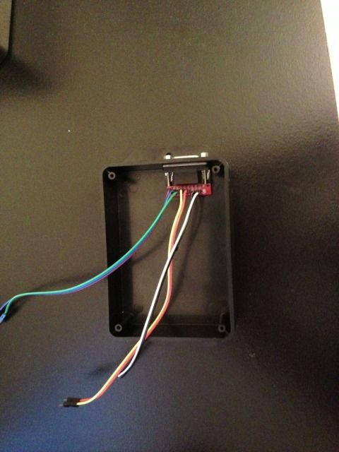
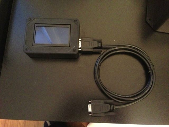
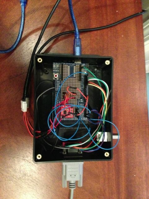
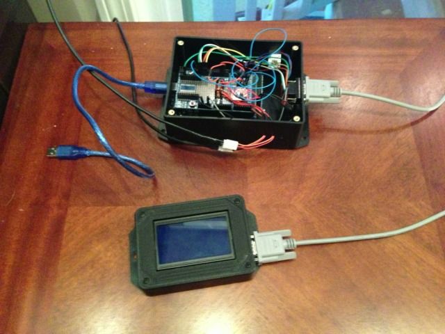
Screen inside enclosure, this will be the only visible part of my controller. I will mount it on the side of the tank. A DB-9 cable will run from this box to the arduino enclosure. Everything will have quick disconnect cables to each other for communications for ease of movement and new programming.

2DEFDA95-CBA5-4C14-B243-0888CDA5A3A3-2060-000000D72F73B216.jpg


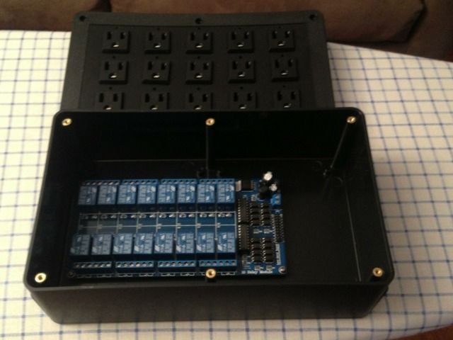
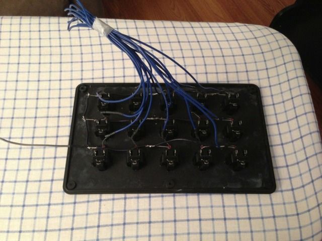
Next I went ahead and mounted my 16 channel relay board into its project box.

60EC5707-6F20-4657-8AE3-97785AC31995-2060-000000D744989FDE.jpg


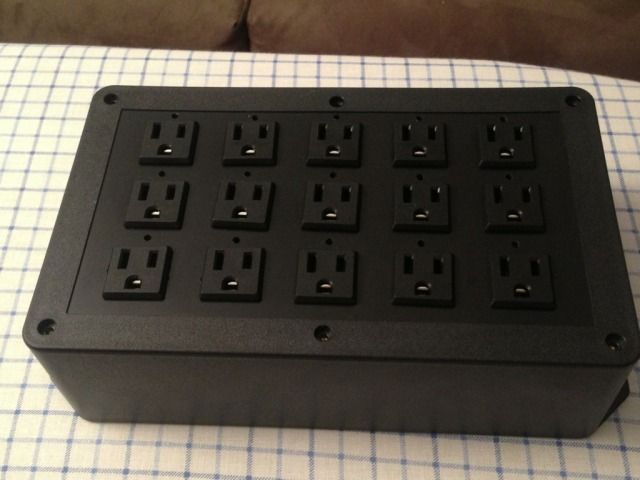
The project box I ended up with allows me to cleanly mount 15 outlets on the front panel. I decided that I would just use 15 instead of the 16 relays. I can always add another outlet to the side of the box if i need that last outlet.

A458C31F-199F-460F-B7E5-E3830FA1B56F-2060-000000D73EB644D5.jpg


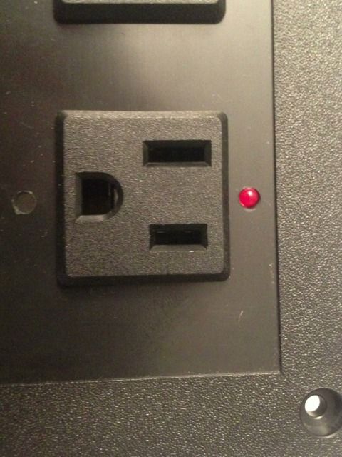
In addition to the outlets I am going to have LEDs mounted over each one to indicate whether or not that outlet is turned on or not.

8B7C0BF9-0552-454F-B1DF-AA85AD8D9456-2060-000000D749B4EC27.jpg


I still need to get some odds and ends parts like wire and connectors to finish up cleaning up everything. I am hoping to get everything mounted in the boxes in the upcoming few weeks and head back to coding. The tank this is going on is not even close to being ready to be setup so I have time to play around with this more before I really need it to be finished.

I have not updated this thread as frequent as I wanted to since I am also trying to finish up some trim in the room where the new tank is going, so please be patient with some of my progress updates.
 
15 relays?! I trust you're putting this somewhere where all the clicking won't make you crazy

They aren't too bad. They will be in the enclosure and under the tank. It should minimize the sound quite a bit.
 
So like I mentioned before, I haven't worked on this all to much as of late as I am really focusing on getting the new tank up and running.
I did take some time out today to keep moving forward with tucking everything away in their enclosures so I can finish up programming.

I pretty much have the screen box all set up. Only thing left for me to do is add a button that will start feed mode.

DB9 connector that will be used to talk to the main Arduino board. This will also carry the signal for the feed mode button.
4F657390-755F-4C92-9A76-2F2B607917E6-9822-0000038E7A46EE1C_zpsb0acf3fd.jpg


Top down view of the wiring of the DB9 connector. The connector is from Spark Fun, it came with all the mounting hardware along with a breakout board for wiring connections.
43AE13D0-38C2-4835-9024-858286B5C6A9-9822-0000038E81B21F3D_zpsc32266da.jpg


View of the complete screen enclosure (minus the feed button which will sit on the top of the enclosure) with its serial connector cable.
0F84DC50-99F9-4C9A-A385-21889C17FEBA-9822-0000038E72A49F0E_zps2ef75c07.jpg
 
Next I started do do the wiring for the LED indicators on the power box which will tell me which outlets are currently turned on.
001350C3-A4C4-4661-BDEE-E63718A6890A-9822-0000038E6BA593CF_zps8b22afcd.jpg


I need to get a few more connectors before I can start wiring up the relays to the outlet. In addition to this I will need to install a DB25 connector which will carry the signals from the Arduino to the control box for the turning on and off of relays. I will also have to install a power jack into this enclosure as well as this is the portion of the controller that will need to be plugged into the wall outlet.
 
Well now that my 120g is up and running, I have some more time to focus on the completion of my controller.

I pretty much have everything all wired up into their boxes. Only thing left is to finish the relay and power center wiring. Once that is done I can finish up with the programming and get this thing on the tank.

Definitely is a lot more work that I figured it would be coming into this. As for final cost I am probably in the $150-$200 dollar range. I have been posting some updated costs as I been posted but I haven't been on top of it like I wanted to. I will go back and do a more accurate costing in the future.

Only other really big addition I would need to do but I am not in a hurry is to develop the pH circuitry. I was thinking about just buying a pre-printed board from atlas scientific but it is a littler pricier.

I think when its all set and done for half the cost I will have he same capabilities and more (minus the internet option) as an apex controller.
 
Feed Mode Button added to the main display that will be going outside the tank.

1D50D006-19A8-4C11-8DC5-246120D791FB-3858-0000018252B221A2_zps5d672d02.jpg


The heart of the controller, the arduino board and proto shield with all wiring for sensors. Only thing left is to wire in the DB25 connector with its appropriate pinouts. This is what will connect the heart of the controller to the power center.

9A9DC121-2C32-4841-B689-EC4EDA10D5FC-3858-0000018210387B4B_zps49b6d8b5.jpg


Shot of the completed display attached to the heart of the controller via a DB9 cable.

B91D3000-AEB7-4F2E-9D37-102376129E45-3858-000001824DE123C7_zps4c3701fe.jpg
 
Looking great! I just ordered a bunch of parts for my arduino controller build, I hope mine comes out as nice!
 
Well sad to say I had to stop with this build. It was consuming a lot of my time and with a wedding right around the corner the wife to be was not happy with any extra time spent on this rather than final wedding planning so I sold all of my components and bought an apex.

I hope at some point I will be able to try and tackle this again.
 
Back
Top